How is the circuit of the loadbank designed?
The circuit of electronic load bank mainly includes four parts: power MOS tube, fixed resistance, PWM drive circuit and sampling circuit. Because the power of a single MOSFET is limited, it is difficult to meet the requirements of power design, so the MOSFET series fixed resistance design is adopted. The MOSFET series fixed resistance is controlled by the MOSFET driving circuit and the output current is adjusted, that is, the
loadbank is composed of MOSFET series fixed resistance.
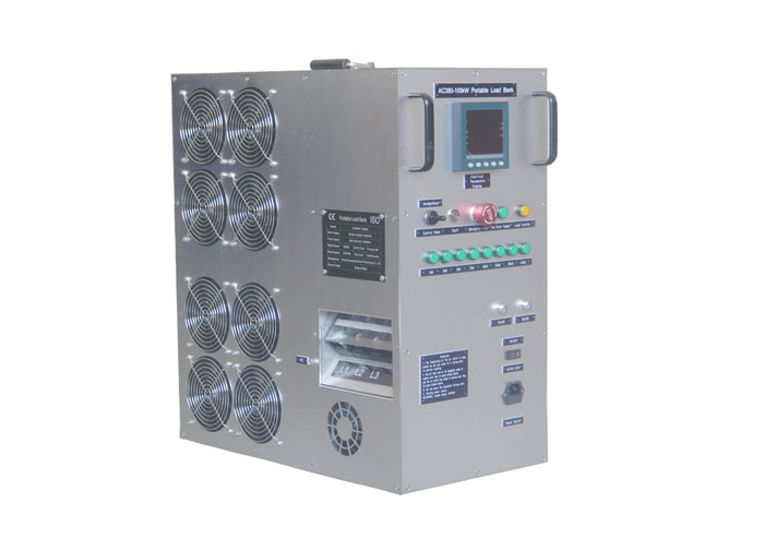
100kw loadbank
Due to the different load cases of working voltage, so need two kinds of MOS tube, DC28V select N channel enhanced field effect tube | RF540N, its maximum withstand voltage 100 v, work under the normal temperature (25 ° C) maximum current 33 a, maximum power 130 w. The N-channel enhanced fET IPW60R037P7 is used for DC270V, with a maximum voltage of 650V, a maximum working current of 76A and a maximum power of 255W at room temperature (25°C). The fixed resistance selects alloy resistance, which is characterized by high heat dissipation performance, strong stability and long service life. Resistance internal selection of high melting point of ni-Cr wire as resistance wire, resistance shell for corrosion resistant stainless steel material, resistance wire and resistance shell between the selection of high temperature magnesium oxide as filler, the load bank is characterized by good thermal conductivity in the premise of satisfying insulation. The resistance is fixed to the stainless steel heat sink. Through the high speed fan to achieve efficient heat dissipation purpose.
Due to the difference in the production process of theload bank, the resistance and inductance inside the MOS tube of the same type will also have individual differences. Therefore, each branch has a sampling circuit and A MOS tube PWM drive control circuit. The single branch PWM drive schematic diagram can be used to monitor the current of each branch by detecting the electrodes at both ends of the sampling resistance R8 in FIG. 15.
Again because the precision and stability of the current sampling resistance is also directly affect the accuracy of measurement, so choose high stability of metal film resistor as current sampling resistance, load cases by PWM signal by the integral circuit response MOS tube output impedance, thus achieve the role of output current regulation, which can effectively prevent the MOS tube for flow.


