Classification of charging pile test load rectifier circuit
A rectifying circuit is a circuit that converts AC voltage into DC voltage. The charging pile test load rectifier circuit can be divided into three types according to the components: uncontrollable, fully controlled and half controlled.
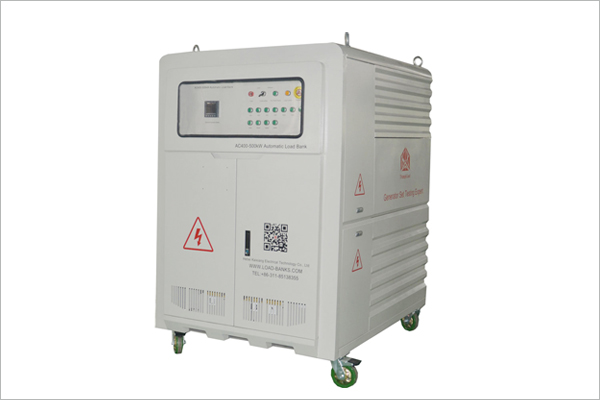
500kw load bank
The uncontrollable rectifier circuit is completely composed of uncontrollable and diode. After the circuit structure is fixed, the ratio of the DC rectifier voltage to the AC voltage is fixed. In the fully controlled rectifier circuit, the power can be transmitted from the power supply to the load, or the load can be fed back to the power supply, which is called active inverter. The semi-controlled rectifier circuit consists of a mixture of controlled components and diodes in which the load power polarity cannot be changed, but the average value can be adjusted.
In order to meet different production requirements, various controllable rectifier circuits have been developed with their own characteristics. Such as according to the circuit structure can be divided into bridge circuit and zero circuit; Single-phase circuit, three-phase circuit and multi-phase circuit can be ranged according to the number of grid phases; According to the control mode can be divided into phase-controlled circuit and chopper circuit; According to the components of the device can be divided into full control circuit and half control circuit.


