Electronic Load Transient Response Test
When the power supply design is completed, it needs to be tested for load transient response, this step is essential. The electronic load has the function of transient response test, which is usually used to test the power supply.
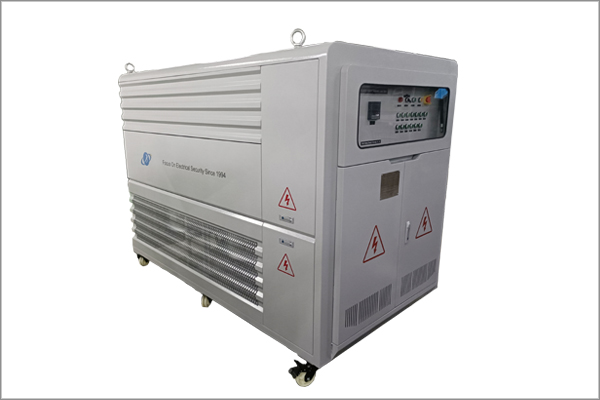
1000kw load bank
The core of the
electronic load transient test tool is the MOSFET power switch under the control of the microcontroller. It operates in both on and off states with a specific duty cycle. When connected to the output of a power supply, the MOSFET conducts a controlled load resistance intermittently connected to the circuit, creating a rapidly changing load pulse. This method produces a very fast load step change rate (approximately 500 ns rise/fall time) and can be used to test any output voltage supply. When such an order load is applied to the output of the power supply, we can analyze the stability of the control loop by measuring the output voltage waveform.
Rapidly changing electronic load trips can affect the controller's control circuitry over a wide frequency range. If the control loop is not stable enough or damped enough, its output voltage waveform will show a ringing signal. This method is only valid in continuous conduction mode (CCM), so discontinuous conduction mode (PSM) needs to be avoided during testing, and the same is true during PSM-CCM conversion, so the adjusted static load needs to be converted Run the system in CCM mode.


